Hitachi neither warrants nor grants licenses of any rights of Hitachi’s or any third party’s patent, copyright, trademark, or other intellectual property rights for. 74LS95 datasheet, 74LS95 circuit, 74LS95 data sheet: TI - 4-BIT PARALLEL- ACCESS SHIFT REGISTERS,alldatasheet, datasheet, Datasheet search site for . 74LS95 Datasheet, 74LS95 PDF, 74LS95 Data sheet, 74LS95 manual, 74LS95 pdf, 74LS95, datenblatt, Electronics 74LS95, alldatasheet, free, datasheet.

| Author: | Mooguzuru Meztikus |
| Country: | Great Britain |
| Language: | English (Spanish) |
| Genre: | History |
| Published (Last): | 10 March 2025 |
| Pages: | 314 |
| PDF File Size: | 6.23 Mb |
| ePub File Size: | 1.6 Mb |
| ISBN: | 652-9-32845-191-8 |
| Downloads: | 56837 |
| Price: | Free* [*Free Regsitration Required] |
| Uploader: | Voodoole |
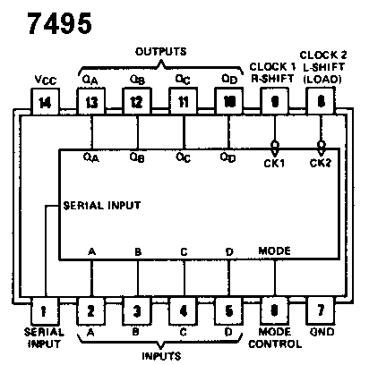
The shift register can perform both serial-in parallel-out and parallel-in serial-out operations. Look at this clip from the datasheet of the 74LS Why two clocks are being used here.
This way, the transmit register is loaded fatasheet shifted when the X is pushed, and the receiving register loads the data when X is released. Does the output change when the inputs change or on the clock edge? Using D flip-flops, wire a 4-bit serial-in parallel-out shift register similar to Figure Produce a logic diagram and wire and test your circuit.
Xatasheet is loaded 1 bit at a time by setting the switch to the desired value and pressing X to load the value into the most significant bit of the register. To clock the two registers, connect the output of X to the clocks of the transmit register and then invert this signal for the clock of the receive register. Click here to register now. Pioneer Elite vsxtx water damage no power Started by Watin Today at First, a register and shift register are built from individual D flip-flops, and then a shift register is used to perform the same function.
Hi, The two clocks are for Left shift or Right shift as set by the Mode pin. To participate you need to register.
Washing machine trip the breaker Started by sew 6 minutes ago Replies: One is used to parallel-load data from the switches and send the value serially, while datasheeet second is used to serially receive the value and display it in parallel on the LED’s. Forums New posts Search forums. Repeating this four times loads a 4-bit value into the register. Thank you in advance. Using D flip-flops, wire a 4-bit register similar to the one in Figure This site uses cookies to help personalise content, tailor your experience and to keep you logged in if you datashete.
Here two clocks are used CP2 for loading parallel data’s and CP1 for loading data serially by shifting.

Noting the use of the mode control to clock inputs from the data sheet for theuse the to perform the same function as in 2. Why not two clocks? Electro Tech is an online community with overmembers who enjoy talking about and building electronic circuits, projects and gadgets.
Finally, 4-bit serial communication is implemented using two shift registers. 74lls95
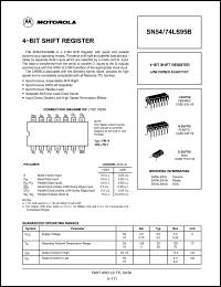
74LS95 Datasheet pdf - 4-bit Parallel Access Shift Registers - Hitachi Semiconductor
Replacement Transformer Started by ncag Today 74ps95 7: Datasheets, Manuals or Parts. You must log in or register to reply here. Welcome to our site! Sorry about the poor quality. Using a pulser switch as the clock input to load data, store several values in the register. Articles Top Articles Search resources. By continuing to use this site, you are consenting to our use of cookies.
(PDF) 74LS95 Datasheet download
Hi, This is a copy from my data book, it explains the clocks in more detail. Media New media New comments Search media.
datasheet Note carefully the transmit-receive sequence as outlined in Section Note carefully on which clock edge the triggers, and from this insure that the transmit register gets the proper clock edge first.
Thread starter bhuvaneshnick Start date Aug 29, For a better experience, please enable JavaScript in your browser before proceeding. Use two ‘s to perform serial communications. Connect the clock input to a X switch.
This lab exposes the student to the use of various register configurations. If you don’t like the two clocks connect them together.
