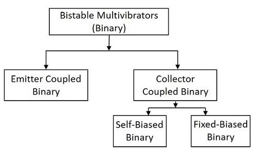
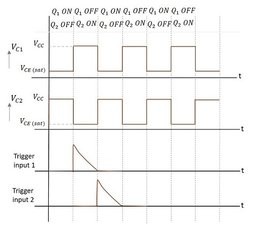
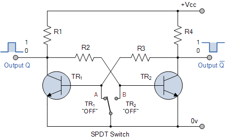
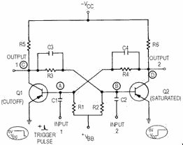
The bistable multivibrator has two absolutely stable states. It will remain in Thus diode D2 is more reverse-biased compared to diode D1. When the positive. BISTABLE MULTIVIBRATOR CIRCUITS The two types of bistable multivibrator circuits considered here are fixed-bias bistable and self-bias bistable. SELF-BIAS BISTABLE MULTIVIBRATORS In a self-bias bistable multivibrator, the negative VBB source can be removed by including an emitter resistor RE.

| Author: | Kanos Daisida |
| Country: | Zambia |
| Language: | English (Spanish) |
| Genre: | Science |
| Published (Last): | 22 April 2024 |
| Pages: | 496 |
| PDF File Size: | 15.87 Mb |
| ePub File Size: | 9.84 Mb |
| ISBN: | 418-6-51253-115-3 |
| Downloads: | 75231 |
| Price: | Free* [*Free Regsitration Required] |
| Uploader: | Daigul |
This is the output voltage of R 1 C 1 integrating circuit.
1) Design a fixed-bias bistable multivibrator using Ge transistors
Q2 begins conducting and this starts the avalanche-like positive feedback process as follows. Thus, Set is used to “set” Q1 on, and Reset is used to “reset” bistagle to off state. Now the transistor Q 1 will be OFF as the base is grounded.

Bistable Multivibrators are used in applications such as pulse generation and digital operations like counting and storing of binary information. The diode will now get reverse biased and the capacitor starts charging exponentially to -Vsat through R.

The resistance R3 is chosen small enough to keep Q1 not deeply saturated after C2 is fully charged. As its right-hand negative plate is connected to Q2 base, a maximum negative voltage - V is applied to Q2 base that keeps Q2 firmly off. Accordingly, one fully charged capacitor discharges reverse charges slowly thus converting the time into an exponentially changing voltage. Similarly, Q2 remains on continuously, if it happens to get switched on first. The circuit stays in any one of the two stable states.
Other applications included early television systems, where the various line and frame frequencies were kept synchronized by pulses included in the video signal. This prevents unwanted frequency switching in Schmitt trigger circuits. So, let us understand this by considering a negative pulse at the base of transistor Q 1.
Views Read Edit View history. Simultaneously, C2 that is fully discharged and even slightly charged to 0. It is a predecessor of the Eccles-Jordan trigger [7] which was derived from the circuit a year later.
Bistable Multivibrator Circuits - Pulse and Digital Circuits [Book]
Another type of binary circuit which is ought to be discussed is the Emitter Coupled Binary Circuit. Thus C2 restores its charge and prepares for the next State C2 when it will act as a time-setting capacitor.
Retrieved from ” https: In the charging capacitor equation above, substituting:. So the output voltage will be. From Wikipedia, the free encyclopedia.
The same Multivibrators are designed using operational amplifiers and also IC timer circuits, which are discussed in further tutorials.
Pulse Circuits Bistable Multivibrator
This is the other stable state. In practice, oscillation always occurs for practical values of R and C. The forward-biased Q2 base-emitter junction fixes the voltage of Biad right-hand plate at 0.
This circuit is considered as a special type of its kind for its applications. If V C is the voltage across the capacitor and from the graph, the time period of the wave formed at capacitor and the output would match, then the time period could be calculated in this way:.
multivibraror
Multivibrator
While not fundamental to circuit operation, diodes multivibator in series with the base or emitter of the transistors are required to prevent the base-emitter junction being driven into reverse breakdown when the supply voltage is in excess of the V eb breakdown voltage, typically around volts for general purpose silicon transistors.
Chaos 22 However, if the circuit is temporarily held with both bases high, for longer than it takes for both capacitors to charge fully, then the circuit will remain in this stable state, with both bases at 0.

Assume all the capacitors to be discharged at first. Please help improve this section by adding citations to reliable sources. The circuit is usually drawn in a symmetric form as a cross-coupled pair.
This technique was used in early electronic organs, to keep notes of different octaves accurately in tune. The output voltage has fixd shape that approximates a square waveform. When the circuit is first powered up, neither transistor will be switched on.
