DATASHEET. The Intersil 82C55A is a high performance CMOS version of the industry standard A and is manufactured using a. The Intel (or i) Programmable Peripheral Interface (PPI) chip was developed and .. , Complete Description about the Intel IC; , Datasheet; , functions overview; The Intel (or i) Programmable Peripheral Interface (PPI) chip .. “PCI A Datasheet” (). 6.

| Author: | Toktilar Tubei |
| Country: | Norway |
| Language: | English (Spanish) |
| Genre: | Love |
| Published (Last): | 3 December 2024 |
| Pages: | 73 |
| PDF File Size: | 15.86 Mb |
| ePub File Size: | 16.43 Mb |
| ISBN: | 526-6-32975-264-2 |
| Downloads: | 18638 |
| Price: | Free* [*Free Regsitration Required] |
| Uploader: | Mijin |
The Intel or i Programmable Peripheral Interface PPI chip was developed and manufactured by Intel in the first half of the s for the Intel microprocessor. The functionality of the is now mostly embedded in larger VLSI processing chips as a sub-function.
Views Read Edit View history. Some of the pins of port C function as handshake lines. For example, if port B and upper port C have to be initialized as input ports and lower port C and port A as output ports all in mode If from the previous operation, port A is datashete as an output port and if is not reset before using the current configuration, then there is a possibility of damage of either the input device connected or or both, since both and the device connected will be sending out data.
In this mode, the may be used to extend the system bus to a slave microprocessor or to transfer data bytes to and from a intl disk controller. Port A can be used for bidirectional handshake data transfer.
Input and Output data are latched. From Wikipedia, the free encyclopedia.

Only port A can be initialized in this mode. This means that data can be input or output on the same eight lines PA0 - PA7. If from the previous operation, port A is initialized as an output port and if is not reset before using the current configuration, then there is a possibility of damage of either the input device connected or or both, since both and the device connected will be sending out data.
In this mode, the may be used to extend the system bus to a slave microprocessor or to intl data bytes to and from a floppy disk controller. For port B in this mode irrespective of whether is acting as an input port or output portPC0, PC1 and PC2 pins function as handshake lines.
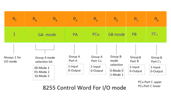
As an example, consider an input device connected to at datasbeet A. The two modes are selected on the basis of the dataheet present at the D 7 bit of the control word register.
Interrupt logic is supported. For port B in this mode irrespective of whether is acting as an input port or output portPC0, PC1 and PC2 pins function as handshake lines. Acknowledgement and handshaking signals are provided to maintain proper data flow and synchronisation between the data transmitter and receiver. The ‘s outputs are latched to hold the last data written to them.
Intel 8255
The is a member of the MCS Family of chips, designed by Intel for use with their and microprocessors and their descendants [1]. This mode is selected when D 7 bit of the Control Word Register is 1.

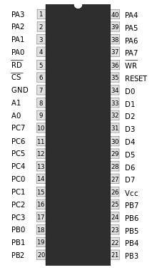
Address lines A 1 and A 0 allow to access a data register for each port or a control register, as listed below:. Retrieved 3 June As an example, consider datssheet input device connected to at port A. Interrupt logic is supported. This is required because the data only stays on the bus for one cycle.
Intel - Wikipedia
Microprocessor And Its Applications. As an example, if it is needed that PC 5 be set, then in the control word. When we wish to use port A or port B for handshake strobed input or output operation, we initialise that port in mode 1 port A and port B can be initilalised to operate in different modes, i.
If an input changes while the port is being read then the result may be indeterminate. For example, if port B and upper port C have to be initialized as input ports and lower port C and port A as output ports all in mode Retrieved 3 June This page was last edited on 23 Septemberat The two modes are selected on the basis of the value present at the D 7 bit of the control word register. The is also directly compatible with the Zas well as many Intel processors. Retrieved from ” https:
