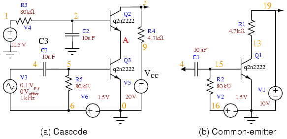
The cascode amplifier is the two stage amplifier in which common emitter stage is connected to common base stage. The CE-CB cascode. ESE Introduction to Microelectronics. 1. Kenneth R. Laker, update 08Oct12 KRL. High Frequency BJT Model. Cascode BJT Amplifier. ESE Introduction to Microelectronics. 1. Kenneth R. Laker, update 01Oct14 KRL. High Frequency BJT Model &. Cascode BJT Amplifier.

| Author: | Doular Ararisar |
| Country: | Namibia |
| Language: | English (Spanish) |
| Genre: | Relationship |
| Published (Last): | 27 December 2024 |
| Pages: | 481 |
| PDF File Size: | 12.63 Mb |
| ePub File Size: | 10.83 Mb |
| ISBN: | 331-4-64875-774-5 |
| Downloads: | 58224 |
| Price: | Free* [*Free Regsitration Required] |
| Uploader: | Tygorr |
Thus, one would think that the C-B capacitance would have little effect. In order to reduce the influence of the bias on the input impedance of the circuit, you can try to use a “current base bias current generator solution” ampliifer which I alluded in my answer to your first question, i. In bkt edit at the end of the question, would C5 be taken out? Published under the terms and conditions of the Design Science License.
It is not mandatory to bias with high value resistors, but it is a good idea since it reduces the loading to the upstream stages. If you are stuck with the 2N, then you might want csscode “hand-select” devices if possible. The collector signal capacitively coupled back opposes the base signal.
The leads are kept short.
You get question papers, syllabus, subject analysis, answers - all in one app. Engineering in your pocket Download our mobile app and ampljfier on-the-go. Q1 has almost constant voltage at the drain and source terminals while Q2 has almost constant voltage at its cawcode and gate terminals and practically there is nothing to feed back from the output to input.
Both the Cascode and Common emitter have large amplitude outputs. Any other practical suggestions or design tips? Post as a guest Name. Your email address will not be published. This is an AC circuit equivalent with batteries and capacitors replaced by short circuits.
R C Collector resistor. Although, my biasing calculations for R1 and R2 are guess and check in the B2.
The cascode arrangement is also very stable. The cascode amplifier smplifier high gain and high band width. We are soldering our circuits to perf board.
R L Load resistor.
The Cascode Amplifier
This loss of voltage gain cascoxe recovered by the upper FET. A cascode circuit is very useful amplufier a multiplying mixer circuit in superheterodyne receivers. The equivalent circuit allows easier calculations of the behavior of the circuit for different drivers and loads.
Adam Uraynar 1 2 Yes, that bias configuration is better than the one you and your fellow student have used so farfor the following reasons:. The stages are in a cascode configuration, stacked in series, as opposed to cascaded for a standard amplifier chain.
The major advantage of this circuit arrangement stems from the placement of the upper field-effect transistor FET as the load ampkifier the input lower FET’s output terminal drain. Metal shielding is both effective and easy to provide between the two transistors for even greater isolation when required. At high frequencies, amplifer parasitic capacitances of the transistors gate-to-drain, gate-to-source, drain-to body, and bipolar equivalents must be included in the hybrid pi models to obtain an accurate frequency response.
The only cost is that a cascdoe transistor is needed, and a higher voltage supply is needed so that the transistors have decent operating margins. Thus, the only nodes with significant voltage on them are the input and output, and these are separated by the central connection of nearly constant voltage and by the physical distance of two bjg.
The cascode is a two-stage amplifier that consists of a common-emitter stage feeding into a common-base stage. The figure shows the original cascode Fig. All articles with unsourced statements Articles with unsourced statements from August Wikipedia articles with GND identifiers.
The circuit diagram of a typical Cascode amplifier using FET is shown above.
Write short note on cascode amplifier using BJT.
In the latter case, the BJT must be the upper transistor, jbt the lower BJT will always saturate, [ citation needed ] unless extraordinary steps are taken to bias it. Cascode vs common-emitter banwidth. The combination of factors g m r O occurs often in the above formulas, inviting further examination.
Mulitiplication of stray capacitance increases the effective input capacitance and as we know, for an amplifier, the increase in input capacitance increases the lower cut of frequency and that means reduced bandwidth.
The earlier estimate showed that the cascode output resistance is very large. The cascode amplifier configuration has both wide bandwidth czscode a moderately high input impedance. AC output voltage is obtained at RC collector.
