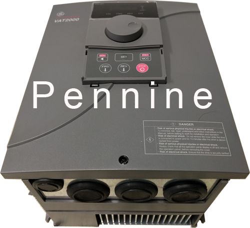
Ge VAT Pdf User Manuals. View online or download Ge VAT Instruction Manual. View and Download GE VAT instruction manual online. AC SPEED CONTROL EQUIPMENT. VAT Controller pdf manual download. GE’s distributor or our sales representatives who will be willing to help you. Please keep GE’s inverters are all passed the function test before delivery. Please.
| Author: | Tygogis Kazshura |
| Country: | Equatorial Guinea |
| Language: | English (Spanish) |
| Genre: | Video |
| Published (Last): | 21 November 2024 |
| Pages: | 186 |
| PDF File Size: | 7.42 Mb |
| ePub File Size: | 14.33 Mb |
| ISBN: | 363-2-89563-956-1 |
| Downloads: | 68376 |
| Price: | Free* [*Free Regsitration Required] |
| Uploader: | Kigakree |
Check the power supply system and correct if necessary. Control Functions and Parameter Settings Block-B parameters The Block-B parameters are divided into the basic functions, extended functions and software option functions. Chapter 2 Installation And Wiring 2. Maximum overload allowed in CT: Primary resistance Inverter Exponent section Page 85 6. Note 7 An output voltage exceeding the input voltage cannot be attained.
The below is an example. Selecting The Setting Data Selecting the setting data Speed setting 1 Speed setting selection The speed setting in VAT is possible from either analog input signals, or from host computer or from the operation panel. Maximum overload allowed in VT: Please speak to us if you require express delivery to these areas.
Forward run Time Page He Page - Adjusting the vector control speed contr The VAT stops with this signal turned off. Test Operation and Adjustment 2 Automatic tuning operation procedures The automatic tuning is carried out according the following procedure. With the VAT, the encoder pulse is defined as shown below during forward run. Refer to section for details.
Page 81 This will affect the current response. Parameter B software option function Parameter C hardware option function One of the two types of inputs can be selected by setting a parameter or with the sequence input.
AC Speed Drive Inverter VATU2KNS GE VATU2KNS *Used* | eBay
Chapter 2 Installation And Wiring Rest of the World and European destinations, days estimated shipment. Page 3 Adjusting the vector control speed control related parameters The reverse run interlock function C may be set or the other parameters may be incorrect. Appendix 1 Type Description System Changes to the Utility Mode. Test Operation With Operation Panel 3. Control Functions and Parameter Settings B Torque setting Refer to section for details on selecting the torque setting.
Increase the acceleration time setting A Don’t show me this message again. Parameter block B02 Accurate motor data setting is required in Vector control.
A drop in voltage, phase dropout or power supply failure may have occurred. This completes changing of the setting value.
VAT2000 AC Drive Series VAT 2000 GE Power Controls
Power Power module fault PM-n. Test Operation and Adjustment Test operation with operation panel The test operation with the operation panel is performed with the following procedure. vzt2000

Precautions For Safety RUN should vxt2000 always ON. Failure to observe this could lead to injuries. VAT O pe n collecto r M ax. Troubleshooting With Fault Display 8. Look for the noise source and remove the cause. Preface Also make sure that this manual is delivered to the final users. All displays are set to skip as the default.
GE VAT INSTRUCTION MANUAL Pdf Download.
Operation Panel Keypad Modes and parameters The parameters to be used differ depending of the control mode C The operation starts from the run speed and operation time applied when the operation was previously stopped. For future var2000 10 Changes to the Monitor Mode. Rest of the World Day estimated shipment. There are a total of nine different setting, all selectable.
Details of Foot print and Stand alone filters are given below. Built in dynamic braking up to 7. Settings Of Data Before Operation Automatic tuning measures the constants of the connected motor, and automatically adjusts the parameters so that the system is used to their maximum performance.
Display 5 digit display and 8 status Led’s. Is possible to set the number of retries, and the wait time t. Drive Parameter control mode: Troubleshooting Troubleshooting with fault display The correspondence of each LED fe and signal is shown in the next page. Autotuning do this automatically.
