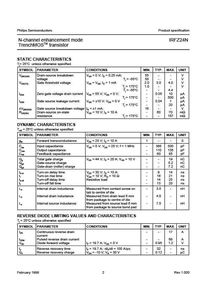
IRFZ22 datasheet, IRFZ22 circuit, IRFZ22 data sheet: IRF - HEXFET TRANSISTORS,alldatasheet, datasheet, Datasheet search site for Electronic Components. IRFZ22 Datasheet PDF Download - (IRFZ20 / IRFZ22) HEXFET TRANSISTORS, IRFZ22 data sheet. IRFZ22 from Motorola Solutions, Inc.. Find the PDF Datasheet, Specifications and Distributor Information.
| Author: | Jusho Gogor |
| Country: | Lithuania |
| Language: | English (Spanish) |
| Genre: | Personal Growth |
| Published (Last): | 14 October 2024 |
| Pages: | 201 |
| PDF File Size: | 10.75 Mb |
| ePub File Size: | 20.42 Mb |
| ISBN: | 831-6-68509-391-8 |
| Downloads: | 45506 |
| Price: | Free* [*Free Regsitration Required] |
| Uploader: | Fenrijin |
The maximum val- ue of the peak point of a current that can safely be passed through a diode in the forward direction. Complement to Process 4P. Noi siamo orgogliosi del nostro successo che fissa per gli altri un traguardo da raggiungere.
The transfer function is: The rectifier regains its reverse blocking capability at time t 2. Referring to Fig- ure 8, gfs equals the change in drain current divided by the change in gate voltage for a constant drain voltage. However, each di- ode must withstand twice the reverse voltage that a diode sees in a full-wave bridge for the same input voltage. Note that since the signal source impedance appears in the td equation, it is very important to pay attention to the test conditions used In measuring switching times.
X suffix letter indicates a 13″ diameter reel with 2, devices. While a high value of VGS th. Line and load regulation are usually better with linear supplies, sometimes by as much as an irfz22 of mag- nitude, but switching power supplies frequently use linear post-regulators to improve output regulation.
Family D4 75 igfz22.
New Jersey Semiconductor IRFZIRFZ22 datasheet pdf
Complement to Process 5Q. Small dataheet resistance of a di- ode operating in the reverse direction determined by the small signal or AC values of reverse current and reverse voltage.
The output ripple frequency is twice the operating frequency datasheett reduces the size of the LC filter compo- nents. Some of the many methods to control minority carrier lifetimes are electron or neutron irradiation and gold or dahasheet diffusion, each with its own advantages and disadvantages. The 4fl typi- cal ON resistance is very useful where switch resistance must be held to an absolute minimum.
Cdg niust not only discharge but its capacitance value also increases since it is inversely proportional to Vdg. Although emphasis is placed on designing and built-in quality and reliability, a complete reliability screening program has been estab- lished.
Switching power supplies are becoming popular because they offer better solutions to these problems. Current flow needed to charge up junction capacitance Cdg acts like base current to turn on the parasitic NPN. The maximum value of di- rect current that can safely be passed through a zener diode in the reverse direction.
IRF TO 40 5 3 2 4 0. Figure 7 shows an expanded view of current commutation, also called reverse recovery. The value of Ir is limited by the circuit, which determines that rate at which stored charge can be dissipated.
Each family is available in 5 configurations. Superposition tests the response of a network to any Input function by replacing the input with an equivalent series of superim- posed positive and negative step functions. It is suggested that the process sheets and specific part number characteristics be consult- ed. Coliector-Base Capacitance Collector-base capacitance measured at some specified collector-base voltage.
To be effective, a program must not only reduce escapes but must also be tailored specifically to detect and remove the types of residual defects that are predicted by process and line monitor control data.
The flyback converter shown in Figure 7 is commonly used in power supplies up through W, which is sufficient for most personal comput- ers, many test instruments, video terminals and the like.

If cur- rent attempts to self-constrict to a localized area, the In- creasing temperature of the spot will raise the spot resist- ance due to the positive temperature coefficient of the bulk silicon. Measured at specified operating conditions and source resistance. The most versatile method of coupling the drive circuitry is to use a pulse transformer.
Half-Bridge Converter This converter Figure 12 operates in much the same fash- ion as the previous push-pull circuit.
New Jersey Semiconductor
For characteristics curves, see Process 1 3. It will operate up to MHz with low noise figure and good power gain. When the transistor switch is opened, inductor current continues to free-wheel through the capaci- tor and diode D2. The center-tapped configuration is pre- ferred for low output voltages since there is just one doide voltage drop.
